

The wiring of transformer differential protection has always been one of the difficulties in relay protection testing, especially for transformers with Y/△ wiring. There is a 30 ° phase difference between the high and low voltage sides, and the calculation and wiring of compensation current are a headache for many beginners. The advantages of the six successive protection tester are most prominent in this situation.
Difficulties in wiring three-phase instruments
When conducting a Y/△ -11 transformer A phase difference test with a three-phase instrument, the typical wiring is as follows: IA is connected to the high voltage side A phase, IB is connected to the low voltage side A phase, and IC is connected to the low voltage side C phase as compensation current - because after the Y/△ conversion on the high voltage side, A phase will produce a reverse current component on the low voltage side C phase, which needs to be compensated.
After measuring phase A, we need to measure phase B, and the compensation relationship is different, so we need to change the wires again. Test phase C and replace it again. The three-phase tester needs to recalculate the compensation relationship and rewire every time it changes phase, which is common for novice engineers to make mistakes.
Wiring of Six Phase Instruments
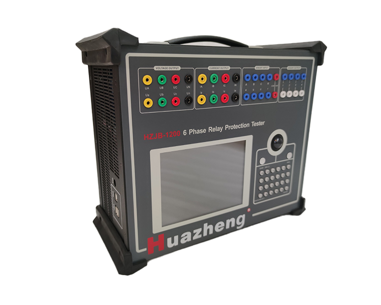
HZJB-1200 performs six phase differential test on Y/△ -11 transformer, with very direct wiring:
Connect the first set of three-phase currents IA, IB, and IC of the tester to the input terminals of the protective high-voltage side A, B, and C phase currents, respectively; Connect the second set of three-phase currents Ia, Ib, and Ic of the tester to the input terminals of the protective low-voltage side a, b, and c phase currents, respectively.
After connection, no changes are required. The internal software of the instrument is responsible for automatically calculating the amplitude and phase of the currents on both sides according to the phase relationship of Y/△ -11. It automatically adjusts when measuring the A, B, and C phases on the high-voltage side without changing the wires throughout the entire process. The value of this advantage in practical work is that the wiring time has been reduced from 30 minutes to 5 minutes, and the error probability is close to zero.
Setting of balance coefficient
The six phase differential test requires the correct setting of the high and low voltage side balance coefficients, which is the key to determining the accuracy of the test results. HZJB-1200 provides four settings: directly filling in the balance coefficient, calculating based on rated voltage and CT ratio, calculating based on primary rated current, and calculating based on secondary rated current. If the fixed value sheet directly provides the balance coefficient, the first option is the simplest; When not provided, fill in the transformer capacity, rated voltage on each side, and CT ratio, and the software will automatically calculate.
Applicable scenarios of three-way current differential
If measuring single-phase differential, or if the differential speed determination value of the measured protection is large (exceeding 30A), it is recommended to use a three-way current differential method - each phase can output a maximum of 40A, which is higher than the upper limit of 30A per phase for six channels, and can cover larger speed determination values.